The touch technology is something very common in our lives nowadays. Elevators, PDA's, cell phones, anything potentially controllable by the end user can incorporate this technology, simple to use but somehow complicated to implement.
The target of this project is to develop a capacitive touch button panel that could be mounted behind any non-conductive surface, mainly plastic and glass. This experiment aims now to produce a 5V signal when a button is touched (or almost touched) but next evolutions of this project should incorporate some kind of communication interface to report button changes to the bus. For example, the addition of a DS2406 would allow the panel to communicate with our opn-one or any other 1-Wire master.
This project came to my mind when I began thinking in the way of putting hidden buttons behind bathroom mirrors and under methacrylate tables. Installing conventional mechanical buttons often affects the aesthetics of the room so why not putting one of this panels instead?
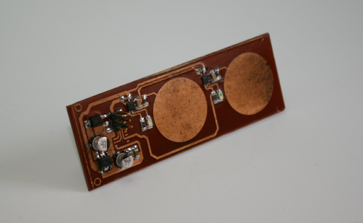
The complexity of the touch panel has been reduced to the minimum. This version is only formed by a linear voltage regulator, two QT100A capacitive detectors, two touch keys directly built on the PCB and two LED's to give visual feedback of the key activation. I will try to post the schema once I tune a couple of capacitor values. Meanwhile, I leave here some pictures of the project and a demonstration video.
Rear view of the panel. The capacitive keys are directly built on the copper layer.
Front view of the panel. As you can see, it is a single side PCB. This side can be
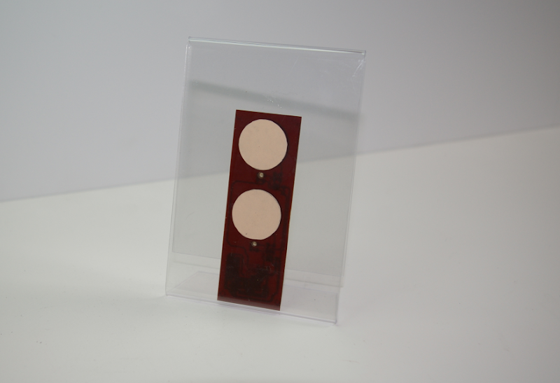
Panel mounted behind a picture frame
This video shows how the panel works when mounted behind a non-conductive surface
Tuesday, 30 September 2008
Subscribe to:
Post Comments (Atom)


3 comments:
HI!
I'm wery interrested in this project! Could You please post the schematics, I'would like to use it in my 1-wire-d house to control lights...
best regards:
Levente Nagy
I am interested in this demo, and want to integrated it into an idea of medical device which helps vision disabilities (blind people). Can you post the schematics?
Thanks,
I've updated my post with the schematics used in this project. Sorry for the delay guys...
Post a Comment